Polyglot signals applied to infrared communications
Introduction
The purpose of a covert channel is to establish a communication link between two entities that are not allowed to communicate, using means that make them undetectable under normal circumstances. As for any communication link, covert channels require at least one receiver and one emitter, that agree on the communication channel and protocol.
This means that at least two devices must be infected and monitor the channel, but those pre-requisites won’t be addressed here.
This post will present the PHY of standard infrared communications, and how it can be leveraged in order to transmit informations while remaining unseen by usual infrared receivers. This proof of concept is part of the broader subject of polyglot signals [1, 2], applied to optical communications.
Today, many devices do have an infrared interface. Be it Smart TVs, cameras, air conditioners, infrared communications are both very frequent and very cheap to play with. This availability and prevalence makes them interesting to transmit data between several devices, even if physically disconnected (air-gapped networks) as they rely on line of sight and not connectivity.
We consider the case of a malware (software or hardware) which would be in control of an infrared LED. The receiver would be a custom-made yet cheap one. This setup can be used to either transmit commands to a device, provided it has been infected at the hardware level with a receiver or to exfiltrate informations from a device.
Infrared in consumer IR
Components
Infrared communications between an emitter (e.g a remote control) and a receiver requires direct line of sight in order to transmit the information. The emission is done using an IR Light-Emitting Diode (LED). The reception is done by a dedicated module, like TSOP38238, VS 1383B, … A photodiode can also be used in order to receive the infrared signal, as some are tailored to detect infrared light.
All those components can be cheaply bought online, for a few euros. Or, they can be harvested from devices around us as they are common use.
From left to right: A 3mm IR LED, a VS 1383B receiver and 2 photodiodes
In order to setup basic IR communications between two devices only a LED and a receiver are needed, hence the ease to play with this communication interface.
PHY
Basically, remote controls send commands to receiving devices by blinking a LED. Those commands are encoded using a pre-determined scheme (not the topic) then modulated over a 38kHz carrier wave.
One frequently used modulation is called On-Off Keying (OOK). To transmit a 1 the LED blinks at 38 kHZ during some time and to transmit a 0 it stays off.
On-off keying in customer IR communications
This shows that IR communications are essentially RF communications and can be manipulated using the same toolset.
Common IR receivers perform this demodulation step: they output the original data directly.
Output of an IR receiver
Crafting a polyglot signal over IR
Polyglot signals are communications that can be decoded differently depending of the PHY of the receivers. Such signals carry several informations and the PHY discriminates which is retrieved. This is very important in the context of covert channels, as it opens up entirely new kinds of RF-based covert channels.
The main idea here is to add another signal over the modulated one such that the legitimate receiver would not detect it, but a custom receiver would correctly decode it. Though I will present only two ways to do so, plenty exist and are viable in this context.
Amplitude Shift Keying (ASK)
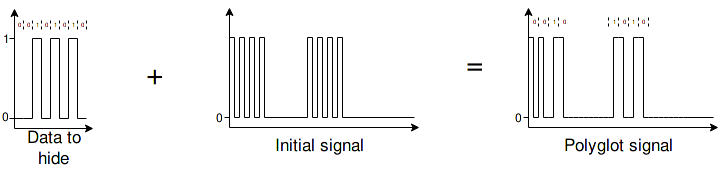
It is possible to add amplitude variations to the signal, slight enough such that the legitimate receiver would only see it as noise. One can encode the data to hide using Manchester to provide interesting properties :
- As there are the same number of 1s and 0s in a Manchester-encoded signal, the mean amplitude would remain constant no matter what the hidden information is;
- Using Manchester, it makes the covert channel more resistant to noise.
Using OOK over OOK to craft a polyglot signal
In the example, the choice was made to encode each 1 and 0 on one period, using On-Off Keying. With this method, the amount of data transmitted depends of the frequency of the carrier wave. Here one can transmit 38 kbps of Manchester-encoded data, that is 19 kbps of raw data.
This method has the advantage of being able to transmit continuously. With slight enough amplitude variations, they should be considered as noise by standard IR receiver, hence remaining under the detection threshold.
Phase Shift Keying (PSK)
Instead of modulating the amplitude of the carrier wave, it is possible to modulate its phase. This works by shifting the phase of the carrier wave depending of the bit to transmit.
A simple way of adding PSK modulation is by shifting the phase of the carrier wave by 90° when transmitting a 1.
Using PSK over OOK to craft a polyglot signal
A potential problem appears here : When transmitting interleaved sequences of 1s and 0s (such as 1010), it is as if the legitimate data was encoded using OOK over a 19 kHz carrier wave.
In the example, one can transmit up to 38 kbps (if the LED is constantly blinking). However, it is hard to determine the average transmission rate in practice, as it depends of external factors. Hence, this method can transmit data somewhere between 0 bps and 38 kbps.
Synthesis
In order to fabricate a polyglot signal suited for IR communication, one can use whichever modulation deemed necessary. Other ways of using ASK, PSK and also Frequency Shift Keying (FSK) could work just as well. Essentially, one is limited only by the properties wanted for the covert channels and by the resources at disposal to establish it.
Proof of Concept
Material required
Infrared communications happen at a reasonably low frequency : 38 kHz. Nowadays, in order to capture and analyze a signal at this frequency, one can use the sound card of a computer. Mine goes up to 192 kHz, which is enough for sampling the signal. For generating the signal, it is possible to use an Arduino connected to the emitter.
Summing everything up, here are the material and resources used :
- 1 Infrared LED (retrieved from a Wii Sensor Bar);
- 1 Infrared receiver (can be retrieved from cheap devices such as DVB-T tuners);
- 1 photodiode (can be retrieved from old devices such as an old hifi stereo);
- 1 3.5mm jack with wire strands (remove insulation from wires with a soldering iron, abrasive paper, …);
- 1 Arduino (Uno here);
- 1 sound card which can sample at least 96 kHz;
- Resistors to protect components
- Several wires.
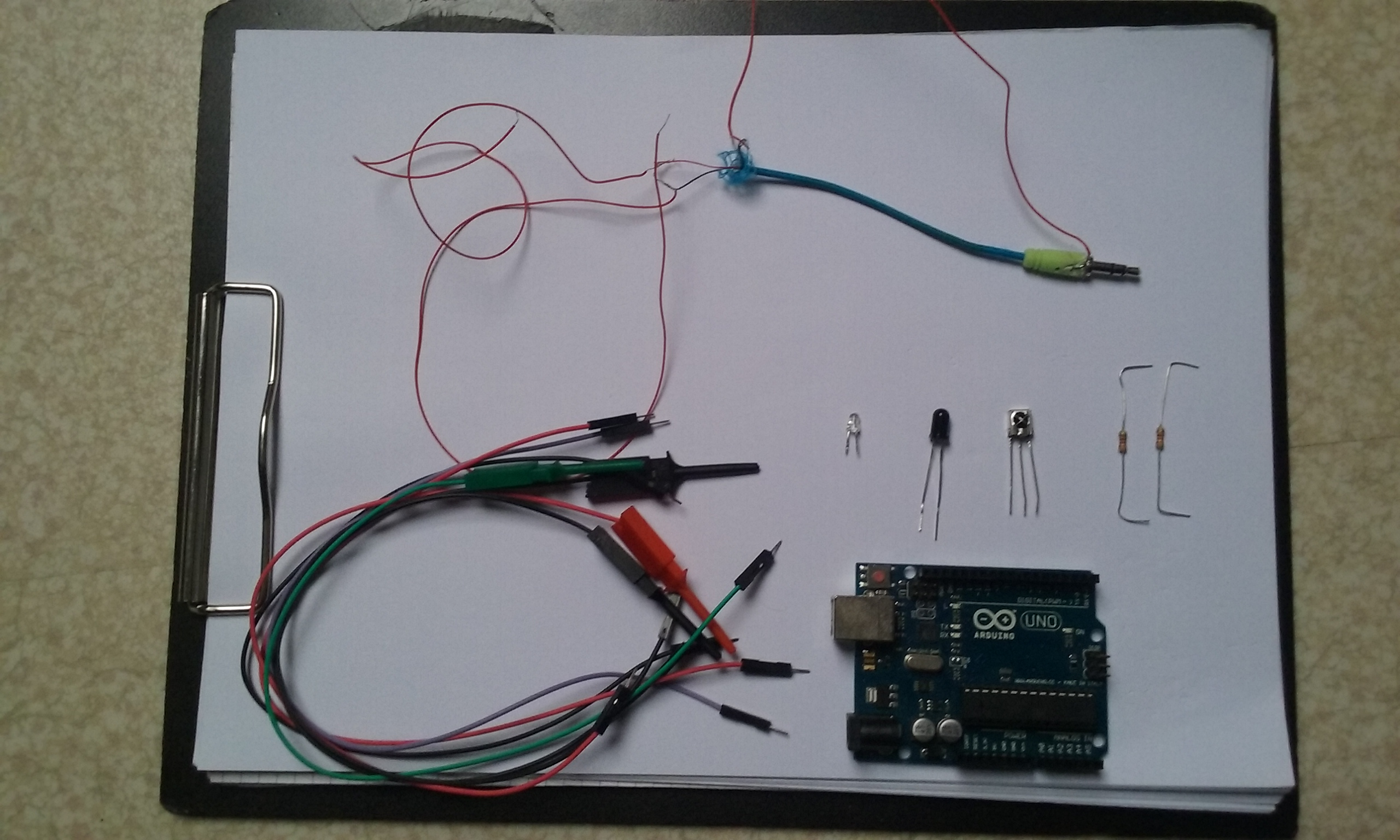
Components required (sound card excluded)
In order to test the components (especially the crafted 3.5mm jack), a signal coming from a remote control was alternatively captured with the photodiode and with the IR receiver. Also, this served as a validation of the test setup and highlighted the modulation in consumer IR.
The captures were realised using the command arecord -D hw:1 -r192000 -t wav -f S16_LE -c2 ir-photodiod.wav and visualised using Audacity.
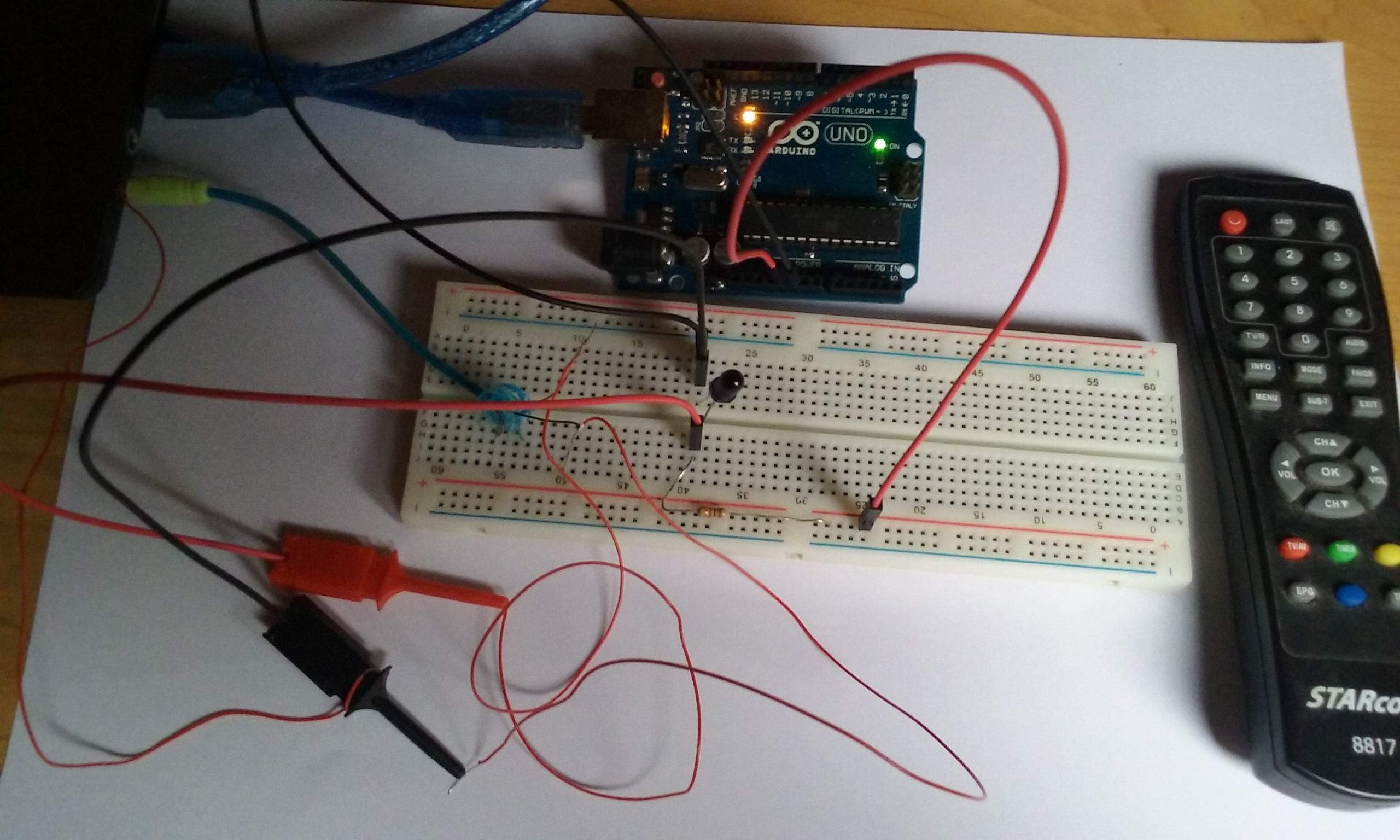
Test setup with the photodiode
For this verification step, the Arduino is used only as a DC generator. The same assembly was used with the IR receiver, simply the signal was sampled on the OUT pin of the receiver.
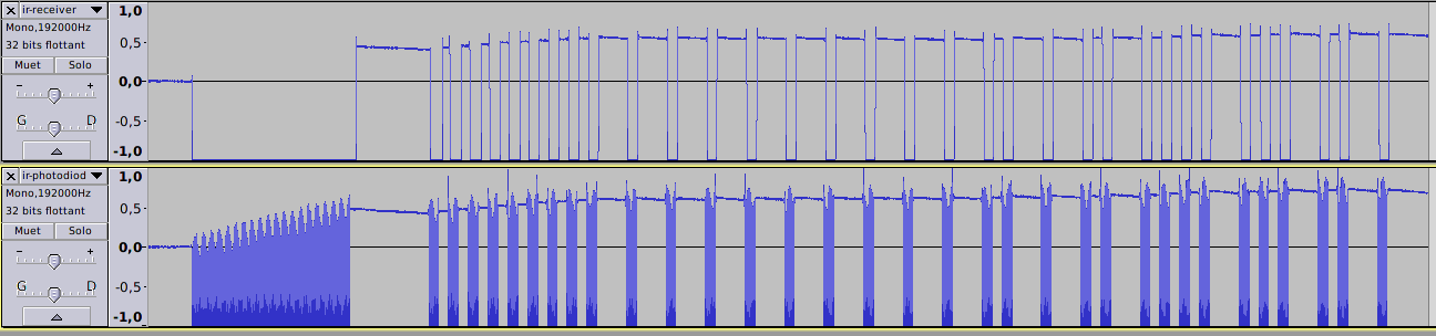
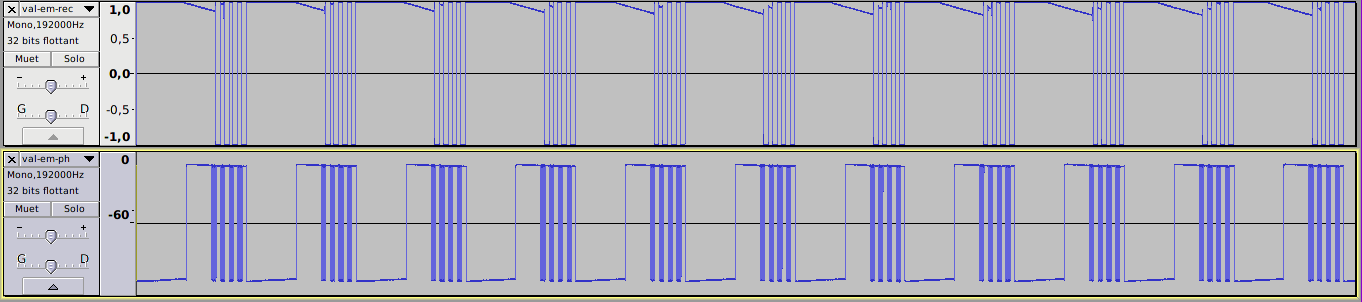
Capture when pressing the '1' button
Those captures indeed validate the test setup. It is easy to demodulate the signals by hand, with each receiver. It seems that the remote used for the test further use the NEC encoding, but no validation has been attempted. Either way, this demonstrates the IR modulation and the frequency of the carrier wave:
The interval between 20 periods amounts to 53 microseconds, which gives a carrier wave of 37.735 kHz, thence close enough to 38 kHz.
Generation of a signal
The receiving toolchain has been validated, now the emission part must be validated too. As the final purpose is to use a specific modulation, no external dependencies are required by sketches. The Arduino is used to emulate a remote, hence will output a modulated signal to an IR LED.
For the moment, the Arduino will output a simple stream of 1s and 0s, modulated by a 38 kHz carrier wave. The period of the signal is ~26 μs. Each bit will be transmitted for 20 periods, that is 520 μs.
The IR receiver needs to detect some sort of preamble before outputting the demodulated signal. Emitting a long 1 followed by a long 0 does the trick. However, without this the OUT pin of the receiver will stay at a LOW state.
Test infrared emission
The sketch played for this capture can be found here. The captures are also available as WAV files: photodiode and IR receiver.
There are two small things to note from this test:
- I couldn’t manage to have a modulated preamble like the remote used for testing. I suspect this is because the IR LED used for emission is greatly under-powered: The Arduino can’t generate a powerful enough signal. This difference is validated by the delta between the intensity observed when using the remote or the Arduino for emission.
- There is a slight delay (few microseconds) for detecting a 1 between the photodiode and the IR receiver. This is usual, according to the datasheet of the IR receiver used.
Despite those, this test shows that it is indeed possible to control PHY of IR communications with an Arduino. Now, we can leverage this ability to forge and transmit some polyglot signals.
The first described scheme for polyglot signals in IR (OOK + OOK) couldn’t be easily implemented with an Arduino. This is because one does not control the current output of a pin sufficiently precisely. At first, the function analogWrite seemed promising, but in reality what one controls with it is the duty-cycle of a signal of 490 or 980 Hz (depends of the pin). So, by doing analogWrite(3, 25), the output is 5V for 10% (25 * 100⁄255) of a period of a 2ms period (1⁄490), then 0 for the rest of the period. However, the principle behind the first scheme was to be able to output different levels of tension like 5V±10% or 0.5V, with a microsecond precision. In the end, this kind of polyglot signal could not be tested.
The second described scheme (OOK + PSK) has been implemented. In order to test in somewhat real conditions, one of the control code of a remote has been re-implemented to be emitted by an Arduino.
The original (demodulated) code is 1010 1010 1010 1010 1000 1000 1000 1000 1000 1000 1000 1000 1000 1000 1000 1010 0010 1000 1010 1010 1000 10. The choice of 624 microseconds (24 periods) per bit was made, which matches the original time of transmission used by the remote. The modulation scheme chosen has the limitation that it is impossible to transmit covert data while transmitting a 0, hence the data can only be transmitted during one of the 29 1s. With 1 bit per period, one can transmit 29x24 = 696 bits (87 bytes) of data. However, for easier decoding, it is useful to start each 1 with a chosen bit in order to synchronize the phase of the decoder with the signal. This leaves 667 bits of data, that is 83 bytes.
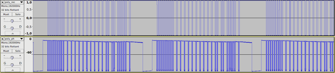
Emission and Reception of a polyglot signal
The signal was generated using this sketch: photodiode capture and receiver capture. The remote control code was successfully emulated by the Arduino, and the original code is easy to retrieve from each capture. This validates that the legitimate signal is properly transmitted.
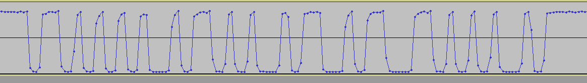
Zoom on the polyglot signal
This is one of the 1s of the polyglot signal as received by the photodiode. The phase differences are also easy to detect visually, all that’s left is to decode them. The program used for performing the demodulation is here. The demodulation implemented is really dumb, that’s why it can miss or add a bit, in which case it throws off the entire command and propagates a lots of errors. However, with a smarter programme, there is little doubt that the rate of errors can be greatly reduced.
$ python3 demod.py polyg-photodiode-capture.wav
Open wav file
Sample width: 2
Number of samples: 1576385
Length of the bytes obj: 3152770

...

b'Hello, World ! this test is meant to educate about covert channels in InfraRed com.'

...

Percentage of decoding errors: 2.16%
In the end, the crafted polyglot signal is properly demodulated by the receiver and by the custom receiver (photodiode + script). Both the initial data and the hidden one are retrieved.
In this proof of concept, the amount of data transmitted has been maximised. With a proper encoding, packet structure and demodulator, it should be easy to greatly lessen decoding errors.
Conclusion
This proof of concept shows the application of polyglot signals to optical communications. Infrared communications are litteraly everywhere and used by lots of devices. This makes it an interesting technology to work with.
This demonstration used only very cheap and common components, but there is little doubt that with more than 20€ of budget one would get more precise results.
Two different modulation schemes have been presented to craft polyglot signals, however the principles presented here apply to a wide range of other modulations and encoding choices.
References
- [1] : https://www.usenix.org/system/files/conference/woot16/woot16-paper-bratus.pdf
- [2] : https://hardwear.io/emmanuel-chaouki-jose.php


